- 您现在的位置:买卖IC网 > Sheet目录340 > MAX15015EVKIT (Maxim Integrated Products)EVAL KIT FOR MAX15015
�� �
�
 �
�1A,� 4.5V� to� 40V� Input� Buck� Converters� with�
�50mA� Auxiliary� LDO� Regulators�
�f� C� occurs� between� f� Z2� and� f� P2� .� In� this� region,� the� com-�
�pensator� gain� (G� EA� )� at� f� C� is� due� primarily� to� C6� and� R5.�
�C8�
�Therefore,� G� EA� (f� C� )� =� 2� π� x� f� C� x� C6� x� R5� and� the� modula-�
�tor� gain� at� f� C� is:�
�C6�
�R6�
�R5�
�C7�
�G� MOD� (� f� C� )� =�
�G� MOD� _� DC�
�(� 2� π� ×� f� C� )� 2� ×� L� ×� C� OUT�
�V� OUT�
�R3�
�R� 5� =� C� OUT�
�Since� G� EA� (f� C� )� x� G� MOD� (f� C� )� =� 1,� R5� is� calculated� by:�
�f� ×� L� ×� C� ×� 2� π�
�C� 6� � G� MOD� _� DC�
�The� frequency� of� f� Z1� is� set� to� 0.5� x� f� LC� and� now� we� can�
�calculate� C7:�
�GAIN�
�(dB)�
�R4�
�EA�
�REF�
�CLOSED-LOOP�
�GAIN�
�COMP�
�EA�
�GAIN�
�C� 7� =�
�1�
�0� .� 5� ×� 2� π� ×� R� 5� ×� f� LC�
�f� P2� is� set� at� 1/2� the� switching� frequency� (f� SW� ).� R6� is�
�then� calculated� by:�
�f� Z1� f� Z2�
�f� P2�
�f� C�
�f� P3�
�FREQUENCY�
�R� 6� =�
�1�
�2� π� ×� C� 6� ×� (� 0� .� 5� ×� f� SW� )�
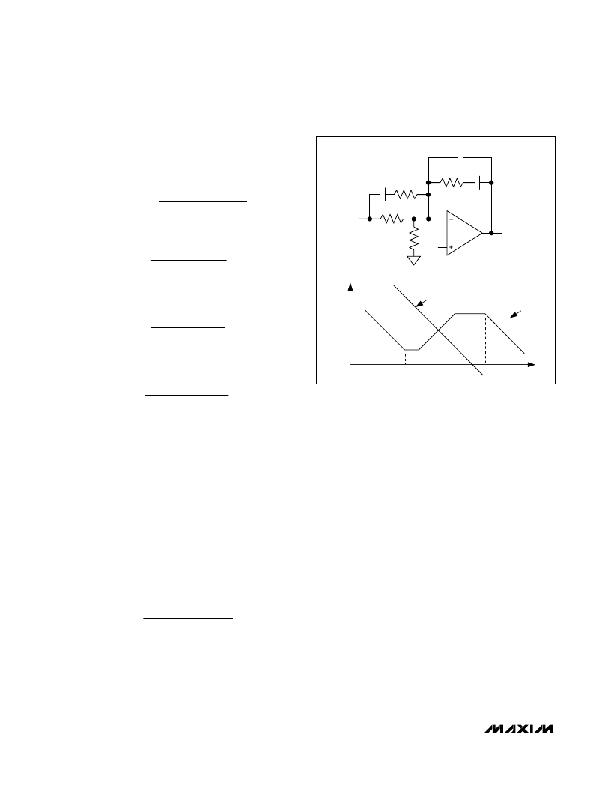
�Figure� 4.� Error� Amplifier� Compensation� Circuit� (Closed-Loop�
�and� Error-Amplifier� Gain� Plot)� for� Higher� ESR� Output�
�Capacitors�
�Note� that� if� the� crossover� frequency� has� been� chosen�
�as� 1/10� of� the� switching� frequency,� then� f� P2� =� 5xf� C� .�
�The� purpose� of� f� P3� is� to� further� attenuate� the� residual�
�switching� ripple� at� the� COMP� pin.�
�If� the� ESR� zero� (f� ZESR� )� occurs� in� a� region� between�
�f� C� and� f� SW� /� 2,� then� f� P3� can� be� used� to� cancel� it.� This�
�way,� the� Bode� plot� of� the� loop� gain� plot� will� not� flatten�
�out� soon� after� the� 0dB� crossover,� and� will� maintain�
�its� -20dB/decade� slope� up� to� 1/2� of� the� switching�
�frequency.�
�frequency� is� higher� than� f� LC� but� lower� than� the� closed-�
�loop� crossover� frequency.� The� equations� that� define�
�the� error� amplifier’s� poles� and� zeros� (f� Z1� ,� f� Z2� ,� f� P2� ,� and�
�f� P3� )� are� the� same� as� before.� However,� f� P2� is� now� lower�
�than� the� closed-loop� crossover� frequency.� Figure� 4�
�shows� the� error� amplifier� feedback� as� well� as� its� gain�
�response� for� circuits� that� use� higher-ESR� output� capac-�
�itors� (tantalum� or� aluminum� electrolytic).�
�Again,� starting� from� R3,� calculate� C6� for� zero� f� Z2� :�
�If� the� ESR� zero� well� exceeds� f� SW� /2� (or� even� f� SW� ),� f� P3�
�should� in� any� case� be� set� high� enough� not� to� erode� the�
�phase� margin� at� the� crossover� frequency.� For� example,�
�C� 6� =�
�1�
�2� π� ×� f� LC� ×� R� 3�
�it� can� be� set� between� 5� x� f� C� and� 10� x� f� C� .�
�The� value� for� C8� is� calculated� from:�
�and� then� place� f� P2� to� cancel� the� ESR� zero.� R6� is� calcu-�
�lated� as:�
�C� 8� =�
�C� 7�
�(� 2� π� ×� C� 7� ×� R� 5� ×� f� P� 3� ?� 1� )�
�R� 6� =�
�C� OUT� � ESR�
�C� 6�
�Compensation� when� f� C� >� f� ZESR�
�For� larger� ESR� capacitors� such� as� tantalum� and� alu-�
�minum� electrolytic,� f� ZESR� can� occur� before� f� C� .� If� f� ZESR�
�<� f� C� ,� then� f� C� occurs� between� f� P2� and� f� P3� .� f� Z1� and� f� Z2�
�remain� the� same� as� before� however,� f� P2� is� now�
�set� equal� to� f� ZESR� .� The� output� capacitor’s� ESR� zero�
�If� the� value� obtained� here� for� R6� is� not� considerably�
�smaller� than� R3,� then� recalculate� C6� using� (R3� +� R6)� in�
�place� of� R3.� Then� use� the� new� value� of� C6� to� obtain� a�
�better� approximation� for� R6.� The� process� can� be� further�
�iterated,� and� convergence� is� ensured� as� long� as� f� LC� <�
�f� ZESR� .�
�20�
�______________________________________________________________________________________�
�发布紧急采购,3分钟左右您将得到回复。
相关PDF资料
MAX15018BASA+
IC MOSF DRVR HALF BRDG HS 8-SOIC
MAX15022EVKIT+
KIT EVAL FOR MAX15022
MAX15025EATB+T
IC GATE DRVR 2CH 16NS 10TDFN-EP
MAX15053EVKIT+
BOARD EVAL FOR MAX15053
MAX15054AUT+T
IC MOSFET DVR HIGH SIDE SOT-23-6
MAX15070BEUT+T
IC MOSFET DRIVER HNM LL SOT23-6
MAX15103EVKIT#
EVAL KIT MAX15103
MAX1554ETA+T
IC LED DVR WHITE BCKLGT 8TDFN
相关代理商/技术参数
MAX15016AATX+
功能描述:直流/直流开关转换器 1A 4.5-40V Input Buck Converters RoHS:否 制造商:STMicroelectronics 最大输入电压:4.5 V 开关频率:1.5 MHz 输出电压:4.6 V 输出电流:250 mA 输出端数量:2 最大工作温度:+ 85 C 安装风格:SMD/SMT
MAX15016AATX+T
功能描述:直流/直流开关转换器 1A 4.5-40V Input Buck Converters RoHS:否 制造商:STMicroelectronics 最大输入电压:4.5 V 开关频率:1.5 MHz 输出电压:4.6 V 输出电流:250 mA 输出端数量:2 最大工作温度:+ 85 C 安装风格:SMD/SMT
MAX15016BATX+
功能描述:直流/直流开关转换器 1A 4.5-40V Input Buck Converters RoHS:否 制造商:STMicroelectronics 最大输入电压:4.5 V 开关频率:1.5 MHz 输出电压:4.6 V 输出电流:250 mA 输出端数量:2 最大工作温度:+ 85 C 安装风格:SMD/SMT
MAX15016BATX+T
功能描述:直流/直流开关转换器 1A 4.5-40V Input Buck Converters RoHS:否 制造商:STMicroelectronics 最大输入电压:4.5 V 开关频率:1.5 MHz 输出电压:4.6 V 输出电流:250 mA 输出端数量:2 最大工作温度:+ 85 C 安装风格:SMD/SMT
MAX15017AATX+
功能描述:直流/直流开关转换器 1A 4.5-40V Input Buck Converters RoHS:否 制造商:STMicroelectronics 最大输入电压:4.5 V 开关频率:1.5 MHz 输出电压:4.6 V 输出电流:250 mA 输出端数量:2 最大工作温度:+ 85 C 安装风格:SMD/SMT
MAX15017AATX+T
功能描述:直流/直流开关转换器 1A 4.5-40V Input Buck Converters RoHS:否 制造商:STMicroelectronics 最大输入电压:4.5 V 开关频率:1.5 MHz 输出电压:4.6 V 输出电流:250 mA 输出端数量:2 最大工作温度:+ 85 C 安装风格:SMD/SMT
MAX15017BATX+
功能描述:直流/直流开关转换器 1A 4.5-40V Input Buck Converters RoHS:否 制造商:STMicroelectronics 最大输入电压:4.5 V 开关频率:1.5 MHz 输出电压:4.6 V 输出电流:250 mA 输出端数量:2 最大工作温度:+ 85 C 安装风格:SMD/SMT
MAX15017BATX+T
功能描述:直流/直流开关转换器 1A 4.5-40V Input Buck Converters RoHS:否 制造商:STMicroelectronics 最大输入电压:4.5 V 开关频率:1.5 MHz 输出电压:4.6 V 输出电流:250 mA 输出端数量:2 最大工作温度:+ 85 C 安装风格:SMD/SMT